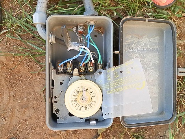
Closed Thread
Results 1 to 10 of 51

Thread: Intermatic Pool Timer Wiring

Hybrid View

  1. #1
    PoolDoc's Avatar
    PoolDoc is offline Administrator Quark Inspector PoolDoc 5 stars PoolDoc 5 stars PoolDoc 5 stars PoolDoc 5 stars PoolDoc 5 stars PoolDoc 5 stars PoolDoc 5 stars
    Join Date
    Jan 2005
    Location
    Georgia
    Posts
    11,207

    Default Re: Intermatic Pool Timer Wiring

    I've got to say, you're making me really nervous. Messing with pool wiring, if you don't know what you're doing, is a great way to hurt yourself, hurt your family, or destroy equipment.

    I deleted 2 of the attachments; they were too small to be very useful. They did provide some info: you have an I-matic T104R timer, which I believe is an 24hr DPST timer. (T104R instructions) And you have a 3/4 HP Whisperflo. More info is needed.

    Let me summarize what I think you've told us; please correct any errors:

    1. You have a 3/4 HP Whisperflo, wired for 120V.
    2. You've used extension cord cable, inside NMT flex conduit. This cable has only 2 wires, and no ground wire.
    + ? Is the extension cord cable coming from the power source (GFCI receptacle) or going to the pump?
    + ? Why are you connecting a pump to a GFCI?
    + ? Why is there no ground wire on one of the connections?
    + ? Why do you have flexible cable INSIDE conduit?
    3. You're installing a metal case T104R timer, which MUST be grounded AND bonded.

    + ? Do you understand the difference between bonding and grounding?
    4. A Whisperflo can be wired either 120V or 240V.
    + ? Are you sure your pump is wired 120V?
    + ? At 120V, all wiring must be 12 gauge, and must not be longer than 100ft total distance from a main power panel. Longer runs must be fed from an intermediate panel, wired with #10 or larger. Have you checked this?
    + ? Do you understand that undersized wiring can 'kill' your pump?
    5. The T104R is intended for use with 220-240V circuits, but can be used with 120V circuits.
    + ? Do you understand the way US 120/240V house wiring is done, with L1, L2, C & Gnd, where L1 <-> L2 is 240V, L1 -> C is 120V, and L2 -> C is 120V and C <-> Gnd is 0V?
    You're a subscriber, so I'm going the distance here with you, but I'm getting the feeling you're in over your head on this one. Please email LARGE pictures to [email protected], and include ALL of the following shots:
    1. Pump motor label.
    2. Over all shot that includes pump, timer, and power source for timer.
    3. Shot of the power source for the timer (GFCI?)
    4. Shot of the end of the 3 wire cord, and also of how that cord relates to the NMT flex conduit.
    5. Shot of the end-bell of the pump, with the electrical cover plate removed, showing the way the pump is wired.
    6. Shot of the pool (what kind of pool do you have?)


    I can't emphasize enough: do this wrong, and the best outcome will be that you destroy your pump. But making mistakes with this could kill a family member -- I mean that literally, not figuratively, as in, "Call the morgue, not the ambulance!".

  2. #2
    Join Date
    Apr 2014
    Location
    Rancho Cordova, California
    Posts
    34

    Default Re: Intermatic Pool Timer Wiring

    The answer to your question about the cable it is a three wire (green, white, black is ground) with a three pronged plug 15A 125V. It isn't an extension cord. I bought one cable and one plug. It plugs into the outlet and has to be connected to the Intermatic Timer to run the pump. If the GFCI receptacle has one of those reset switches correct and it was used for another pool pump. The flexible cable is 12 gauge. It is inside because the 12 g cable has a three prong plug at the end of it to run the timer and the pump. The cable is less than five feet long. An electrician installed the plug to run another pool pump for a 30+ long above ground pool. The person who owned the pool before me had a cable with a plug that provided the electricity to the timer. The pool is a Legacy Laguna soft side portable above ground pool 13w x 21L x 48D. I do understand what can happen if wired incorrectly and how dangerous it is. I won't plug it in until it is wired correctly and someone else checks it if you don't think I've done it right .

  3. #3
    PoolDoc's Avatar
    PoolDoc is offline Administrator Quark Inspector PoolDoc 5 stars PoolDoc 5 stars PoolDoc 5 stars PoolDoc 5 stars PoolDoc 5 stars PoolDoc 5 stars PoolDoc 5 stars
    Join Date
    Jan 2005
    Location
    Georgia
    Posts
    11,207

    Default Re: Intermatic Pool Timer Wiring

    OK. pictures, pictures, pictures.

    I think I have an idea what needs to be done, but it will require some changes, and I won't know till I see the pictures requested. But, the info you provided added a question:

    + ? Has the circuit you have ever been used on this pump?
    + ? If not, what are the listed run amps on the motor AND the listed run amps on the previous motor? (One way to answer is simply to include large pictures of both labels.)
    + ? On the 3-wire cable, you say "black is ground". Why is that?
    (Blue is NOT a standard color, but is usually a power wire. However the B-W-G colors in a mfg'd cable ARE standard, with black=line (120V), white=common, and green=ground. That is what SHOULD be the case. It is dangerous to leave wiring in another state, because workers or homeowners at a later date are likely to assume that the standard will prevail.)

    I just checked your picture again; I can see the black wire now that I look for it. Why in the world would you connect black to ground?

    I'm sorry, but you are scaring me a lot with stuff like that. Right now, I'm very reluctant to give you instructions, lest it lead to someone being injured or killed. I have *personally* been nearly killed, twice, by bad do-it-yourself wiring on pools, and twice more (in years past, when I worked a plumber) by fly-by-night electricians or maintenance men cutting corners. One of those occasions was the origin of my hatred of conduit grounding! I also -- myself -- nearly killed a lifeguard, by not thinking through what could go wrong with a vacuum cart I made, even though that cart was 'code-compliant'.

    Every body thinks it won't happen to them: I know better.

    Is it totally out of the question to hire an electrician?

  4. #4
    Join Date
    Apr 2014
    Location
    Rancho Cordova, California
    Posts
    34

    Default Re: Intermatic Pool Timer Wiring

    I am not sure if my reply to this thread went through. Please disregard if you have. I do know that green is always ground. I thought it was strange. At least I made sure the black ground is connected to the green ground in the timer. The three prong plug had a hole label for each color. I must of misread it. I will fix it. I sent the pictures.

  5. #5
    Join Date
    Apr 2014
    Location
    Rancho Cordova, California
    Posts
    34

    Default Re: Intermatic Pool Timer Wiring

    I forgot to tell you that the GFCI receptacle has not been used for this pump. It was used for a pump I had over thirty years ago. I fixed the plug cable and made sure green is ground from end to end.

  6. #6
    Join Date
    Apr 2014
    Location
    Rancho Cordova, California
    Posts
    34

    Default Re: Intermatic Pool Timer Wiring

    I found some instructions for wiring the timer and it works. I attached a picture of it wired correctly but hadn't set the tripper pins. The timer keeps turning off and turning on for a minute or five minutes, or 15 to twenty minutes before I set the tripper pins. After I set the tripper pins the timer still turns off and on like before. Does anyone have any idea why and how to fix it. Thank you. I attached some photos of the timer and my pool system.
    Attached Images

  7. #7
    PoolDoc's Avatar
    PoolDoc is offline Administrator Quark Inspector PoolDoc 5 stars PoolDoc 5 stars PoolDoc 5 stars PoolDoc 5 stars PoolDoc 5 stars PoolDoc 5 stars PoolDoc 5 stars
    Join Date
    Jan 2005
    Location
    Georgia
    Posts
    11,207

    Default Re: Intermatic Pool Timer Wiring

    The timer should not toggle without trippers in place. If it's doing so, the timer mechanism must be bad. The silver handle, just above the white wire in the photo, is the manual trip. Try toggling it back and forth -- it should turn the pump on, and then off, but should not be loose or floppy.

    If necessary, you should be able to take this model:
    Intermatic-T104-208-277-Volt-Mechanical-Switch
    and swap the guts out, without having to rewire the box.

    If you want a whole new timer, you'll need one like this, with an outdoor case:
    INTERMATIC-T104P3-TIMER-INDOOR-OUTDOOR
    Last edited by PoolDoc; 06-29-2018 at 06:32 PM.

Closed Thread

Posting Permissions

  • You may not post new threads
  • You may not post replies
  • You may not post attachments
  • You may not edit your posts